Sopwith Camel – Final Assembly
Continued from: Sopwith Camel – More Challenges??
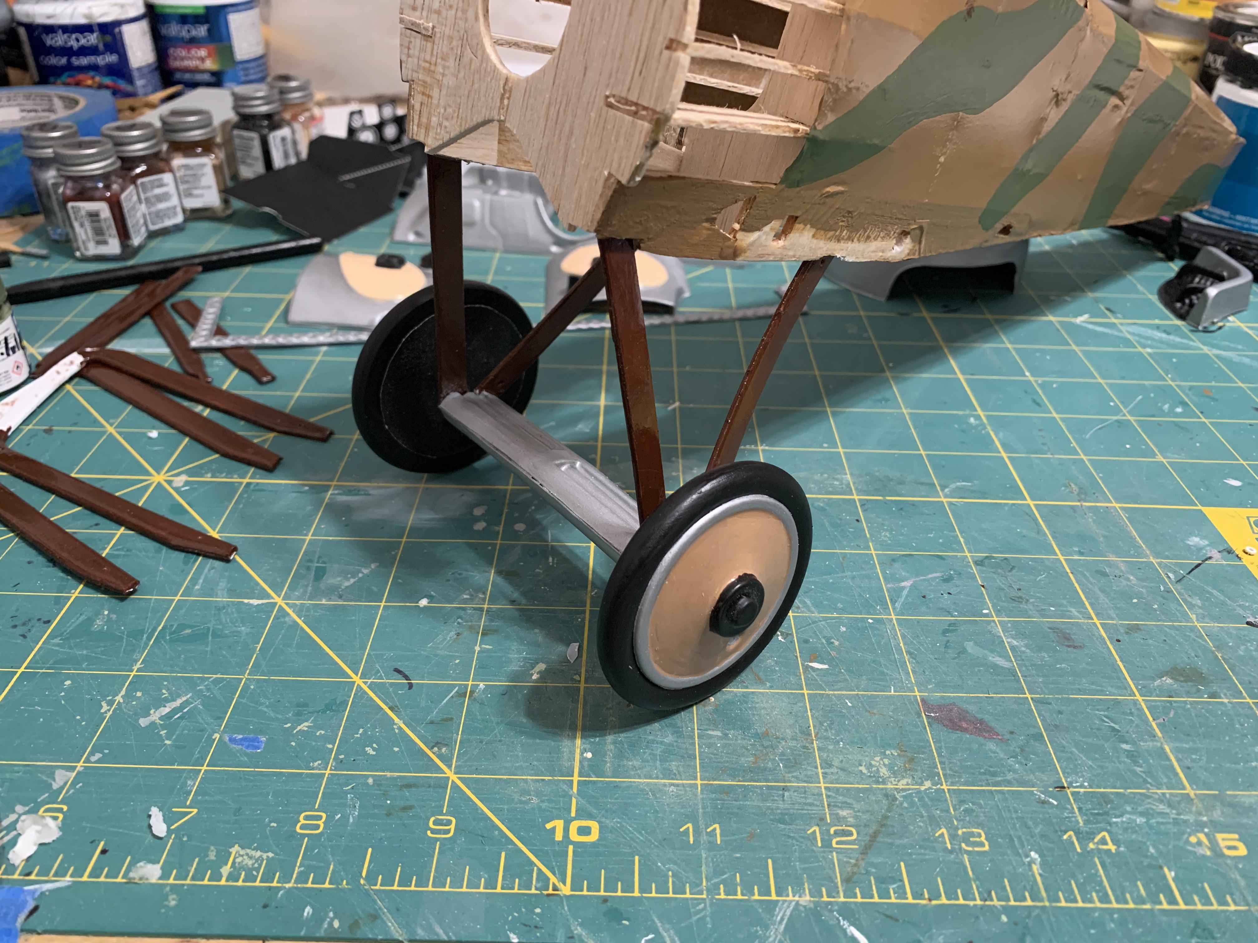
Before I could begin assembling the model, I realized that I needed to prepare the landing gear and wing struts for assembly. In earlier versions of the model kit, these pieces were made from 1/16-inch plywood sheets as they needed to be stronger than the balsa wood used throughout the model. In this modern update to the kit, these parts were die cut into the same thickness of vinyl plastic.
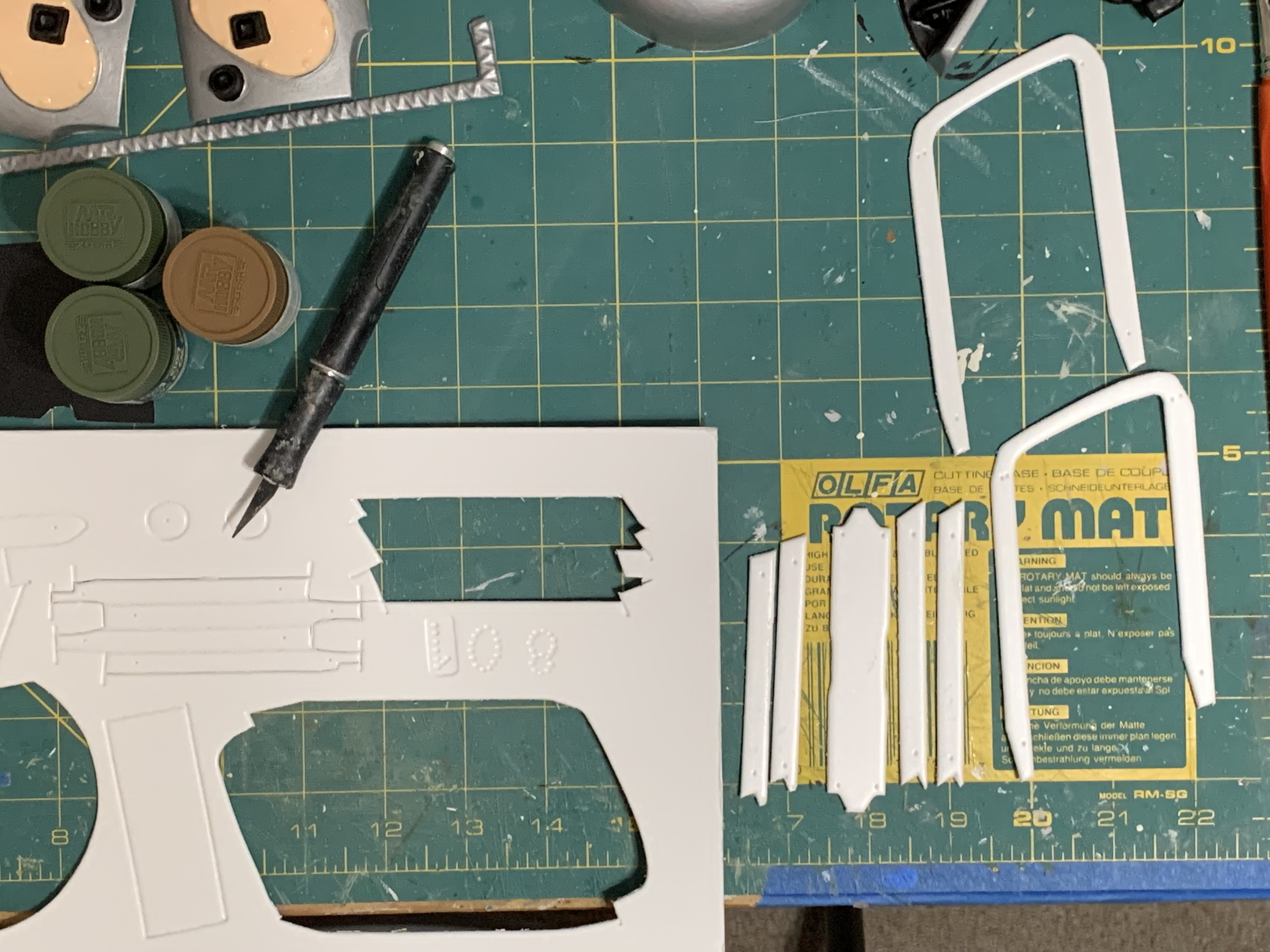
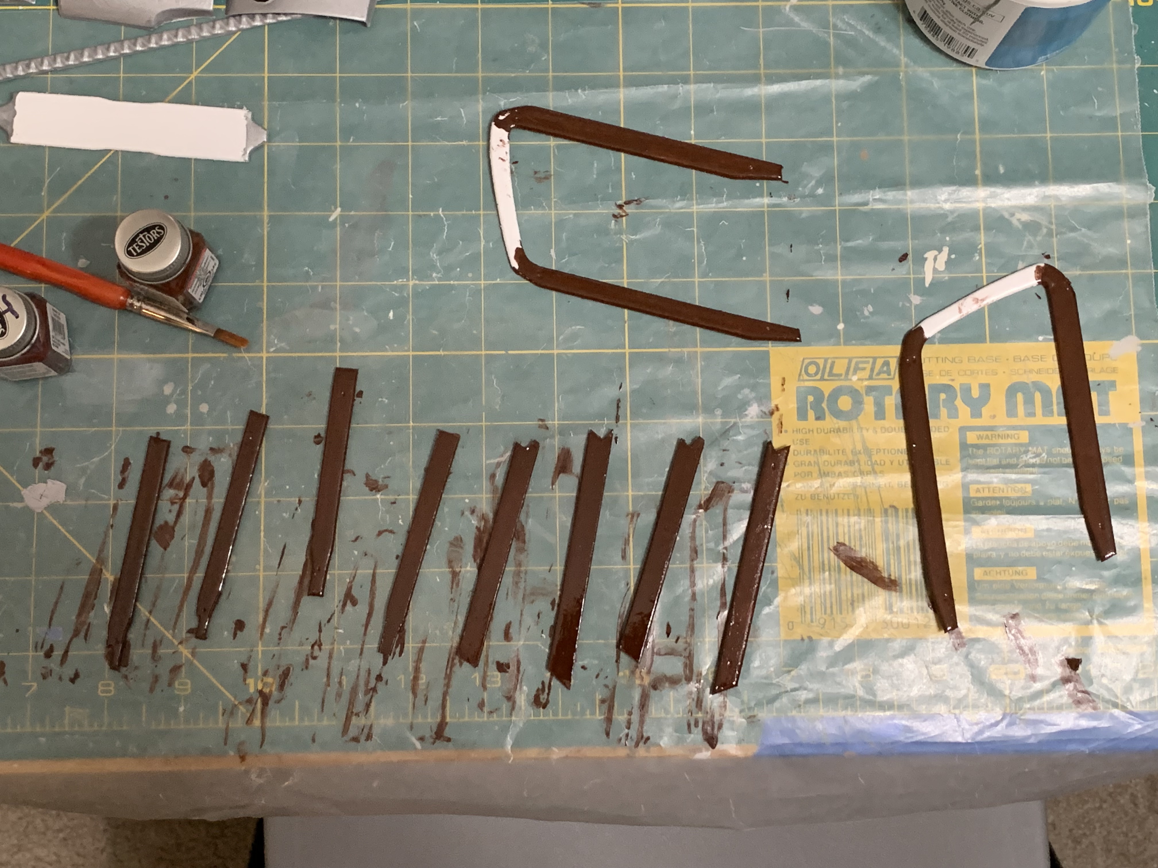
The first step was then to carefully remove each piece from the vinyl sheet and then sand the edges smooth. Had these pieces been made from the plywood, I would have stained them with a dark finish since they had the texture of wood. To make these plastic parts look like wood, I found a really dark brown paint that I had bought and used on some other plastic model I had built. Two coats of this paint gave me parts that looked fairly close to wood.
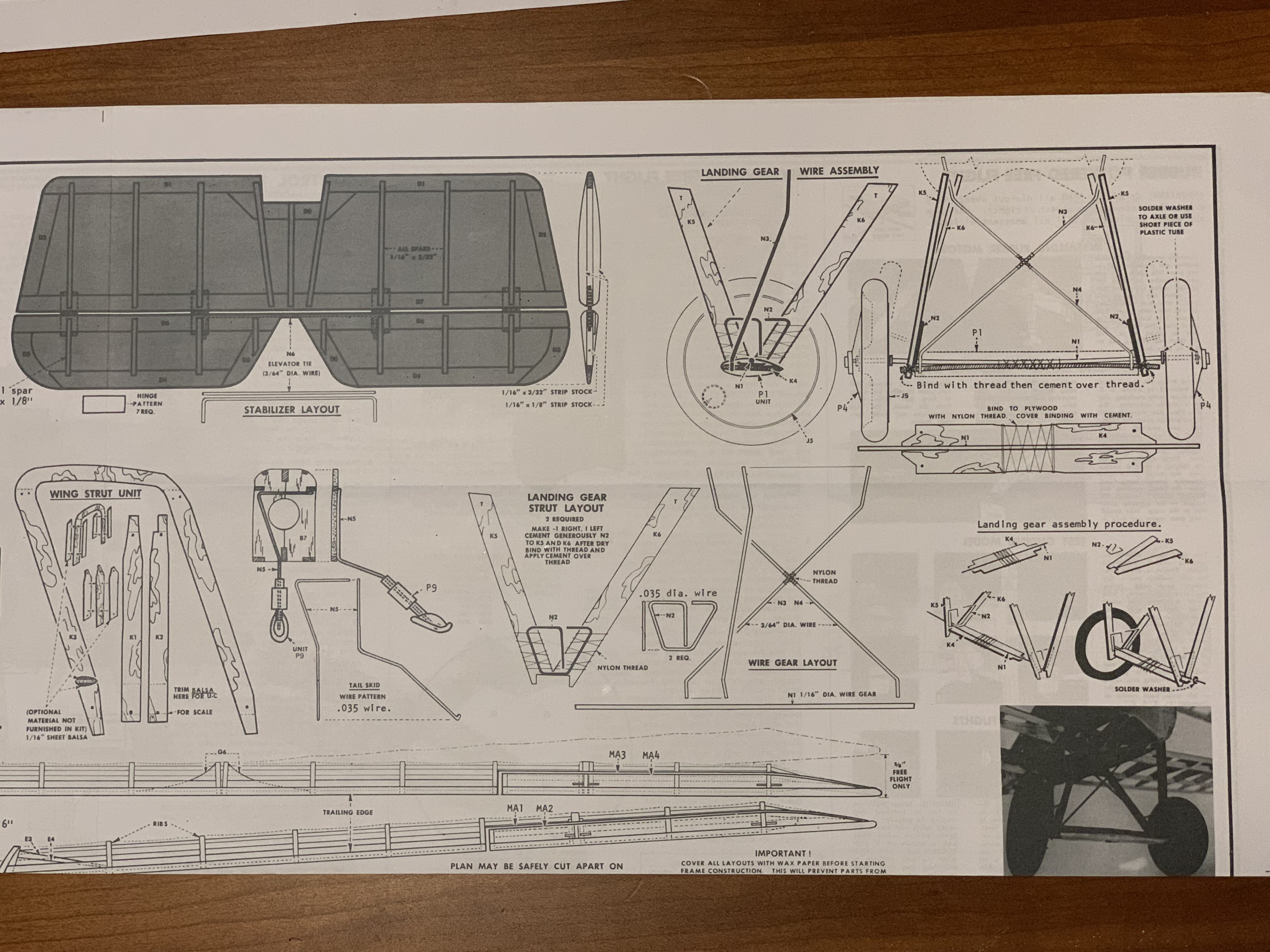
As seen in the instruction photo above, there are several subassembly steps that need to be performed on the landing gear to get it ready for attachment to the bottom of the fuselage. As I struggled with the first step of gluing the struts to the twisted wire piece, I realized that this construction was really to provide some “shock absorbing” capacity for a flying model. Since I was building a static model, I did not need to incorporate these metal pieces and so chose to pursue a modified approach.
It was almost my undoing trying to simultaneously glue five pieces of plastic together but after repeatedly gluing my fingers together with the super glue, I was finally able to get it assembled and attached to the fuselage.
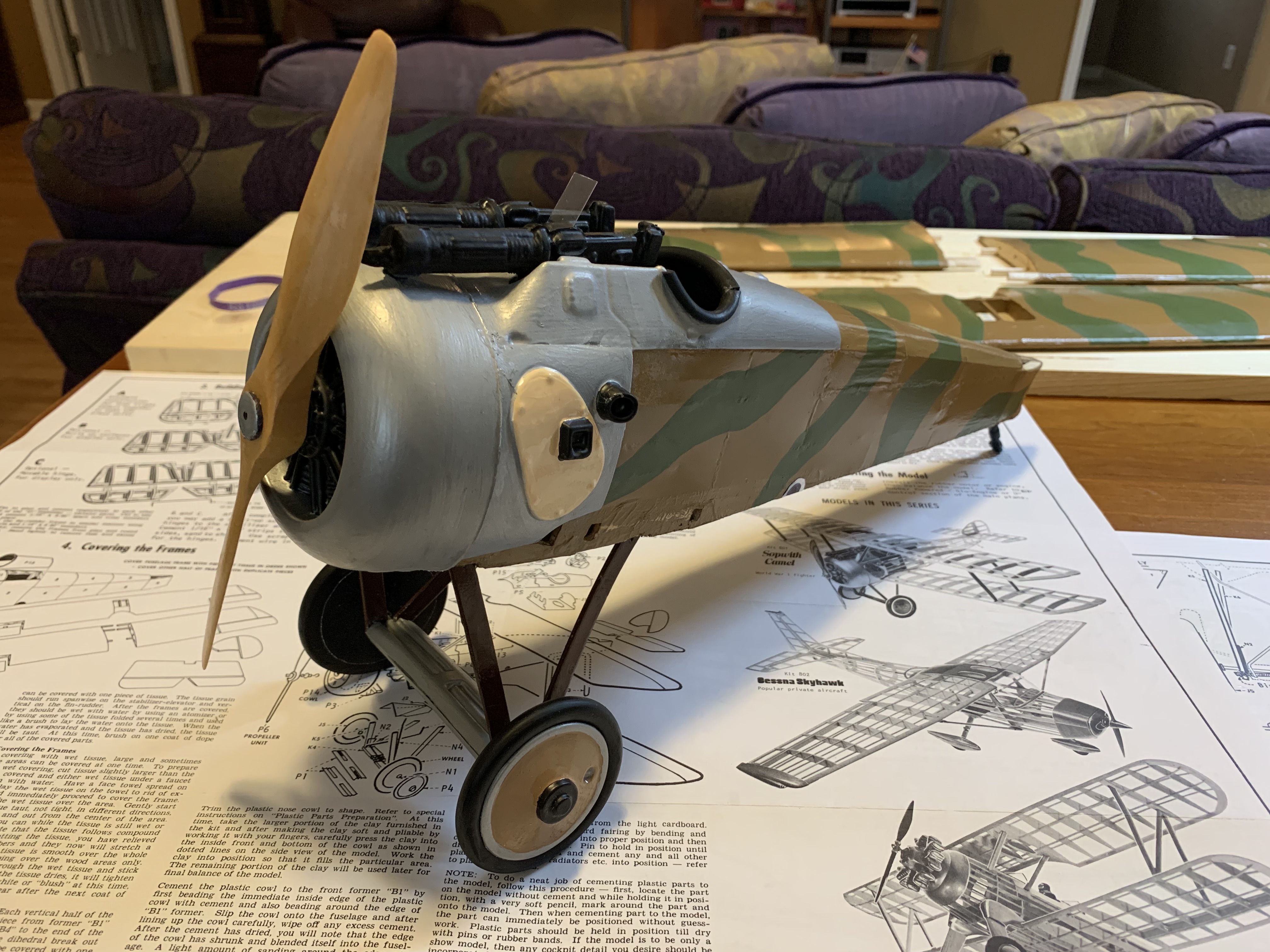
In the instructions, there were no numbered steps providing an order of assembly. So, I had to figure out where to begin myself. It seemed finishing out the fuselage made the most sense, so I started there. With the landing gear securely attached, the remaining pieces to glue on were mostly plastic panels.
First came the cockpit, then the two side panels, then the nose cowling. I had previously glued a screw through the back of the nose cowling to hold the propeller in place. The last step was to glue the two machine guns to the front of the cockpit along with the clear windshield. Once everything was dry, the fuselage was finished.
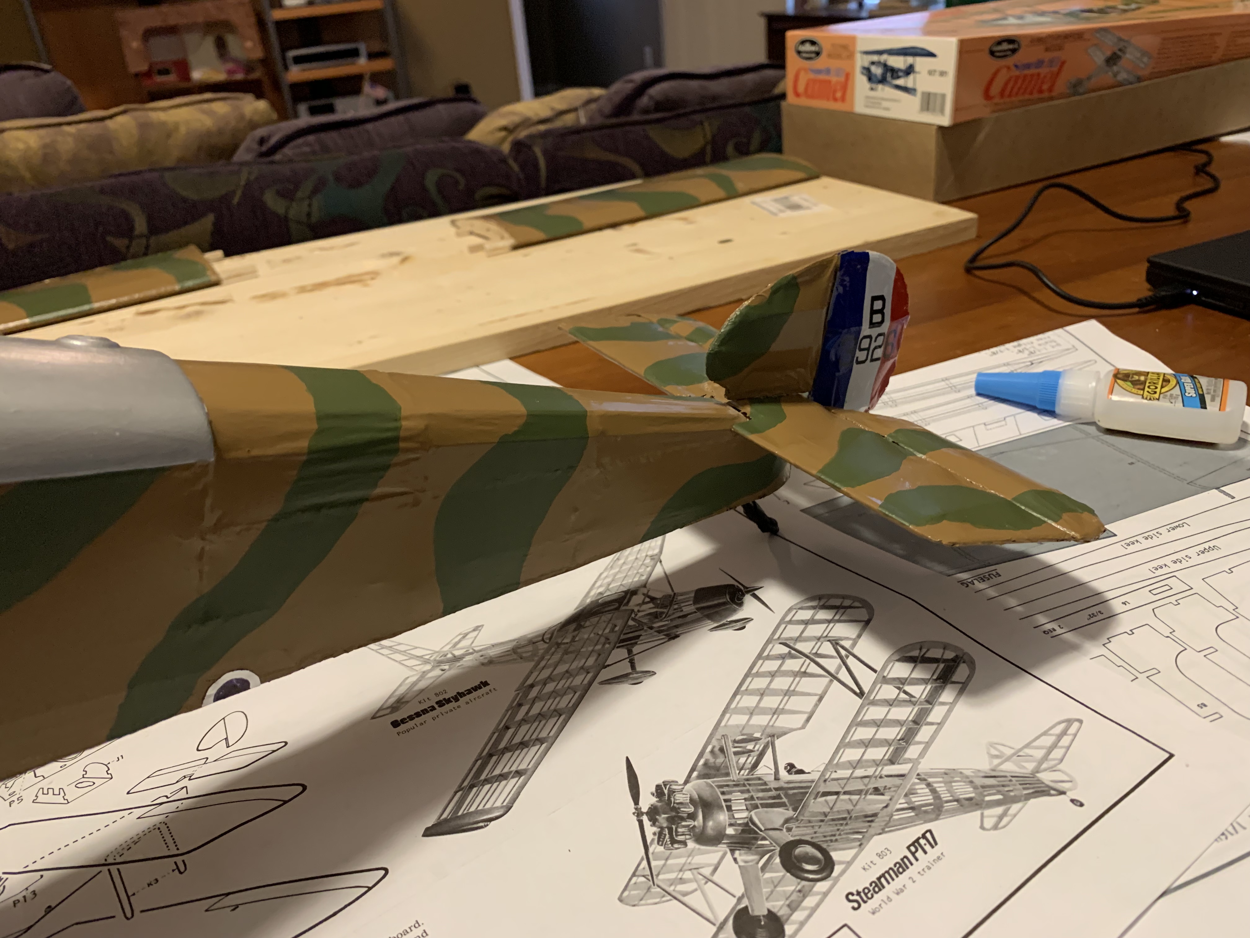
Next up was the horizontal and vertical stabilizers at the rear of the plane. When I glued the horizontal stabilizer in place, it seemed a bit crooked. When I tried to straighten it, I accidentally punched a hole in the top of it. Argh, this is delicate material!
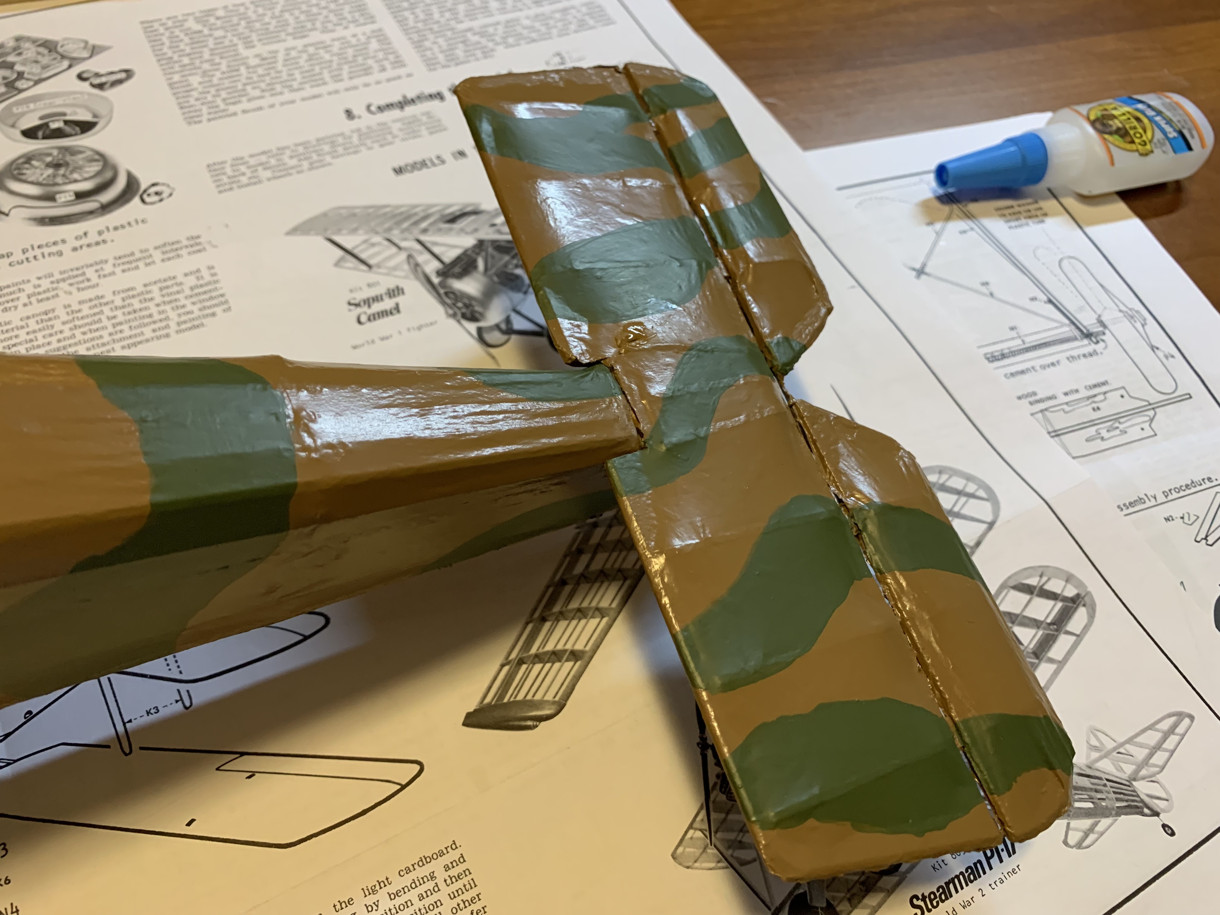
I patched the hole with some glue and once dry, would add some paint to hopefully hide it. Then when I went to attach the vertical stabilizer, the small metal rod that connected the movable control surfaces of the horizontal stabilizer stuck out too far preventing the bottom hinge from attaching to the bottom of the fuselage. I had only added that movable feature to make the plane look more realistic.
Considering several options, I finally decided to notch the vertical stabilizer to accommodate the wire and thus allow the hinge to attach to the fuselage. Although applying decals was the last assembly step, I went ahead and added these to the tail as they would have to be notched as well. With both decals applied, I could then glue the last tail piece in place.
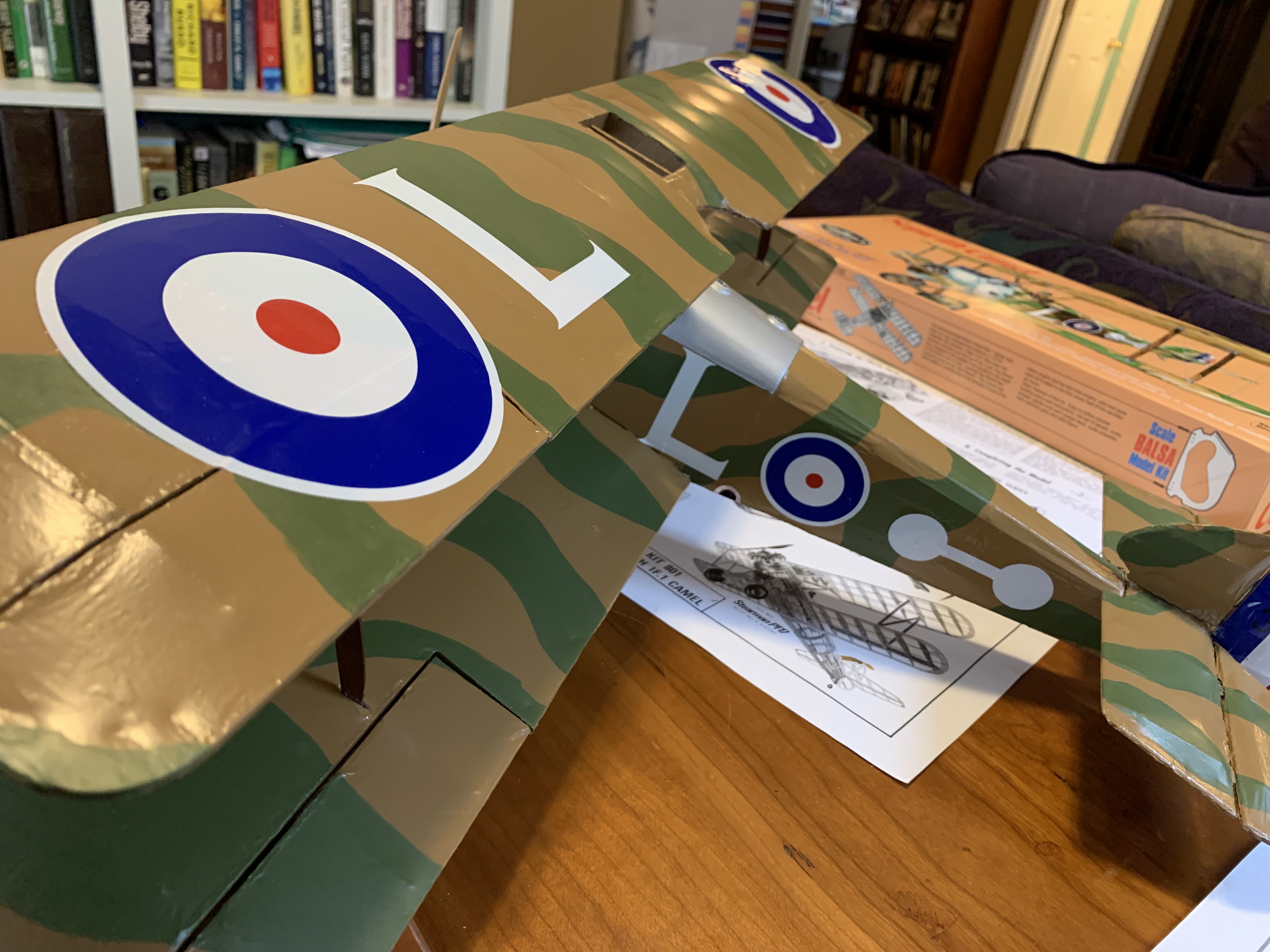
Attaching the top wing to the bottom wings proved challenging as well since I had made a mistake very early in the framing. I had unwittingly run the front spar the length of the wing whereas it was supposed to have a gap between the outer wing and inner wing to accommodate the plastic strut. In the photo below, the errant spar is visible beneath the unpainted tissue.
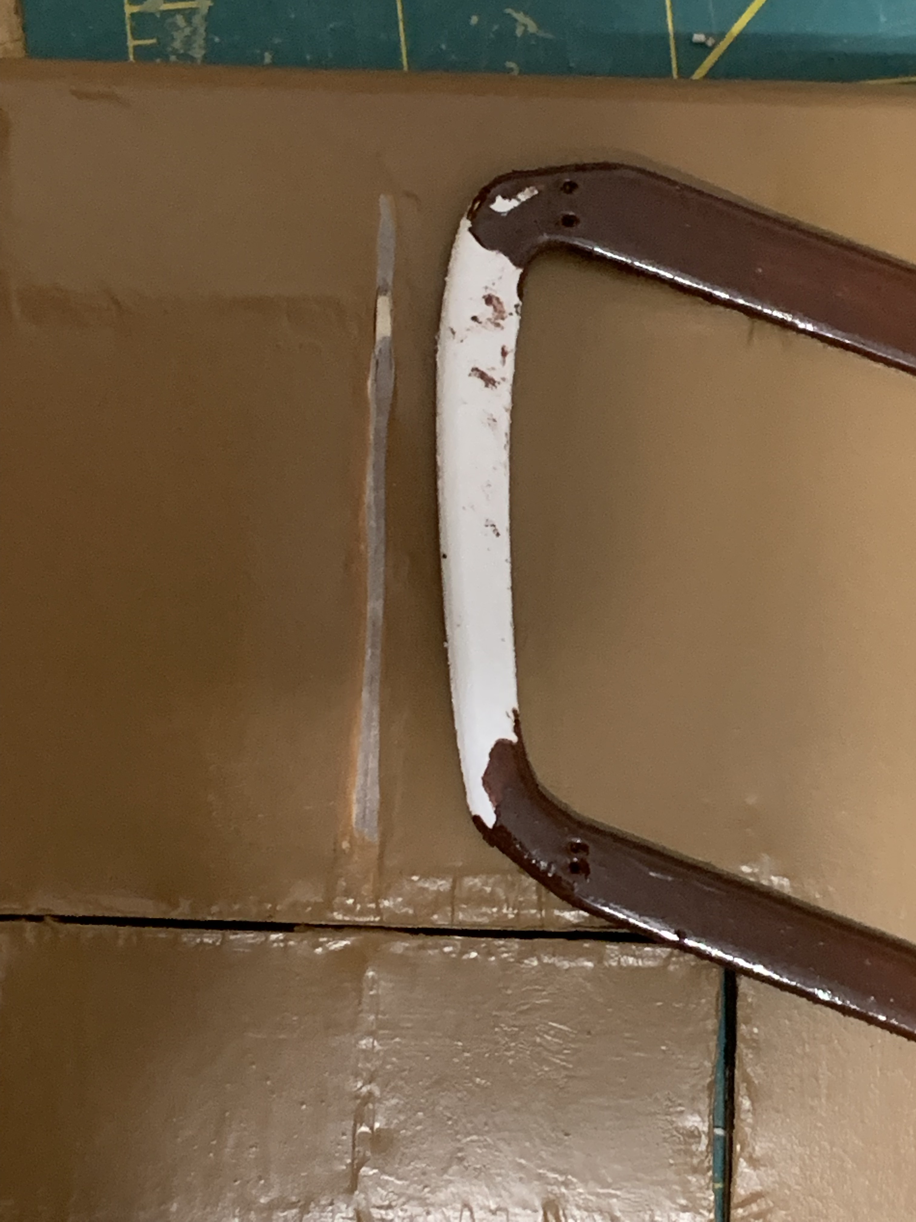
I had to carefully cut it out without cutting all the way through to the tissue on the top of the wing. Thankfully balsa wood is easy to cut through. I also cut down the top of the strut slightly to allow it to fit flush with the underside of the top wing. I figured it would be easier to glue the struts to the underside of the top wing with it flush on my work surface. Once the glue had dried, I painted the plastic connecting section of the struts to blend it into the underside of the wing.
The next step was to attach the upper wing to the lower wings where it would connect at two points on both the left and right lower wing. When I test fit the upper wing, all four points did not make contact with the small holes in the lower wings. Just one more challenge. To remedy this, I first glued the struts to the right wing, let them dry, and then glued and braced the struts to the left wing.
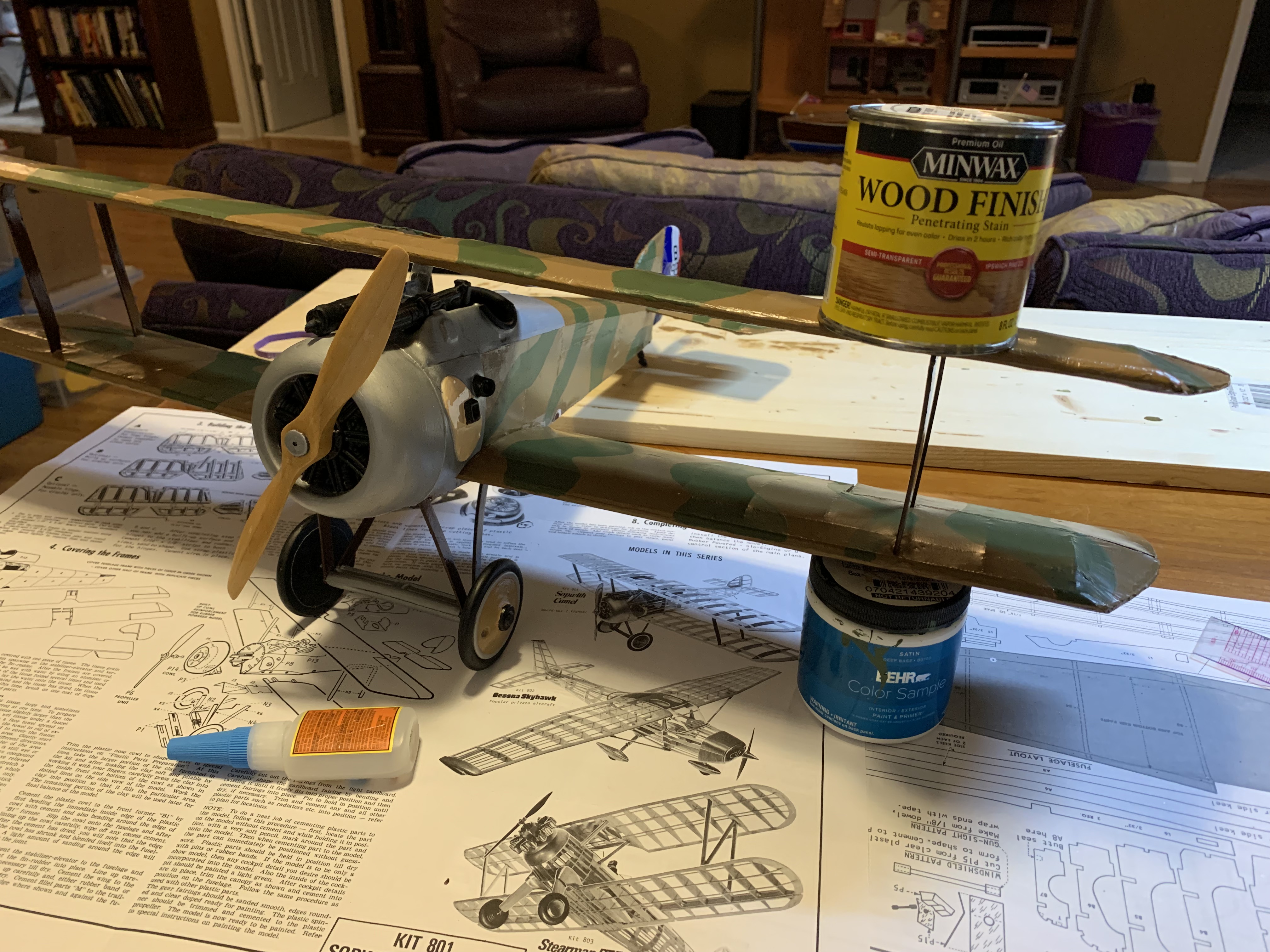
The last four braces (two left and two right) fit into small holes in the upper wing and then attached to the cockpit cowling. This would make eight points of contact securing the two wings together. Test fitting the front two struts, I discovered that they were too long pushing the upper wing up so far, it wrinkled the tissue on the bottom wings. Double argh!
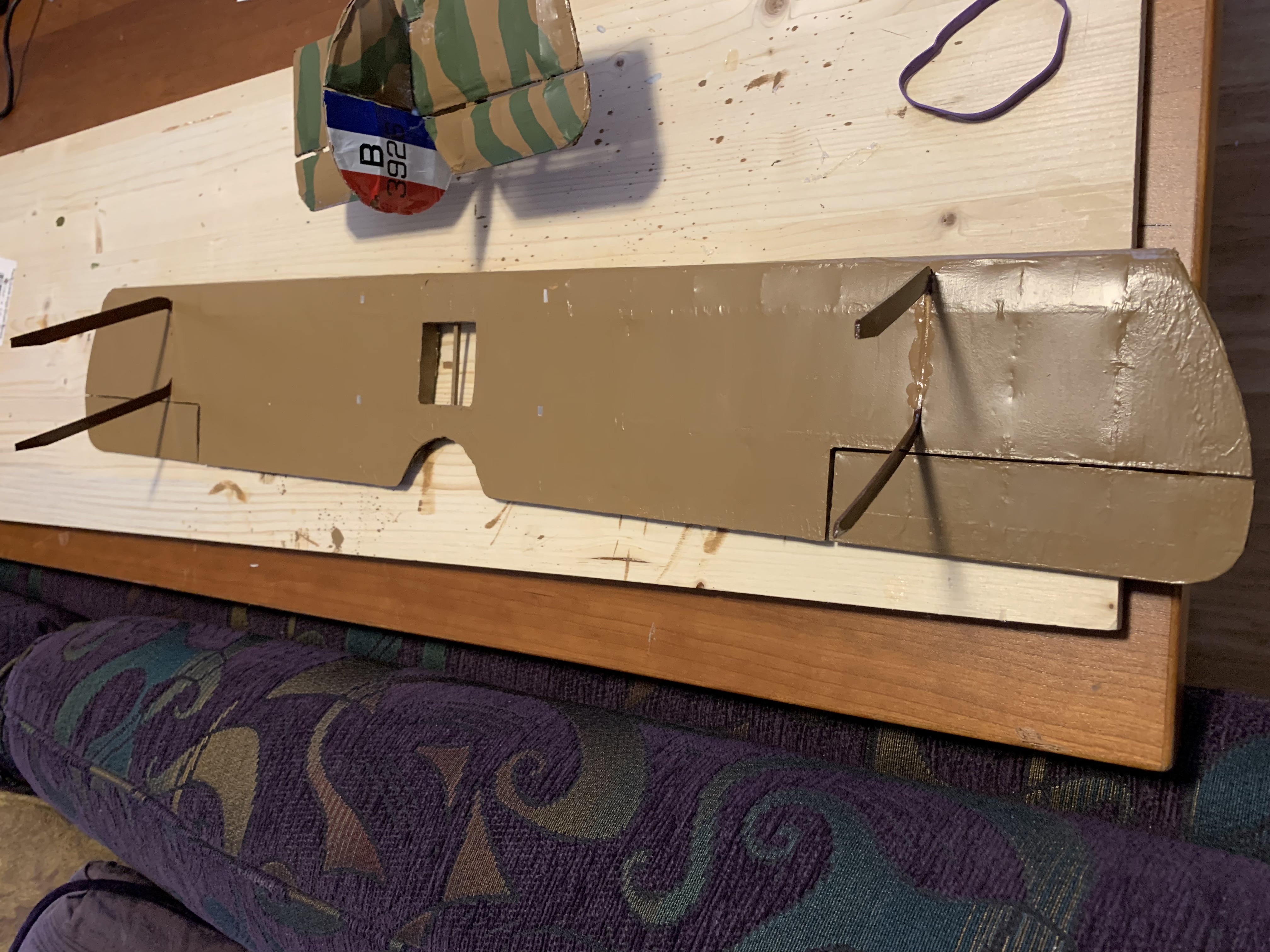
Rereading through the directions to see if I had missed some important detail, I could not find any instructions indicating the struts would need to be shortened. Not knowing the source of my error, I simply needed to figure out how much of the bottom of each strut I needed to cut off. Rather than just guessing, I decided to cut templates from the same plastic material and progressively shorten them until it did not wrinkle the bottom wing.
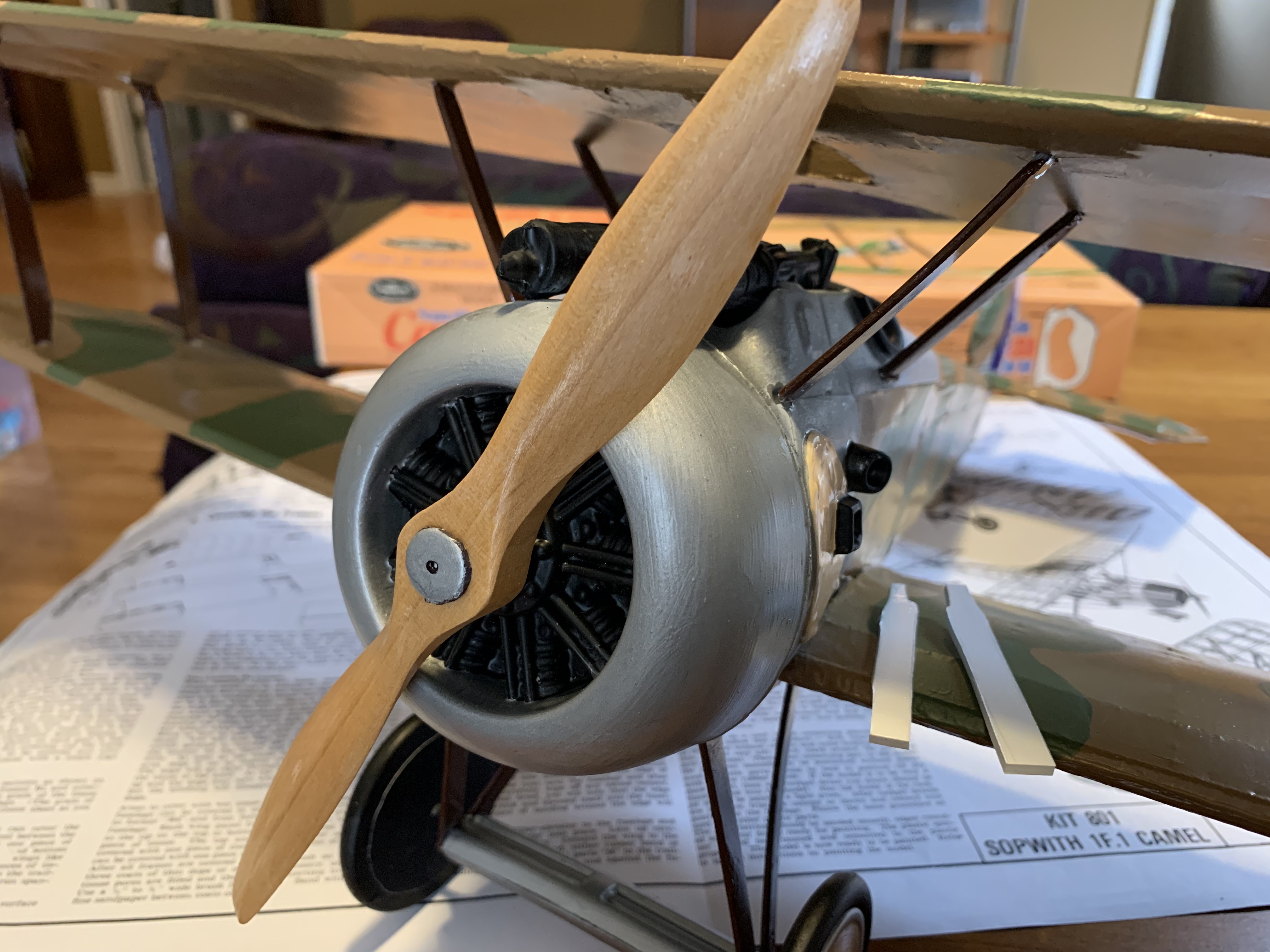
After cutting the templates progressively shorter and shorter and almost poking a hole in the tissue on the top side of the upper wing, I finally got all four glued in place.
The absolute last step (for me) was then to apply the decals.
I could have added the fine thread included in the kit to simulate realistic rigging wires between the wings like seen in the box photo, …
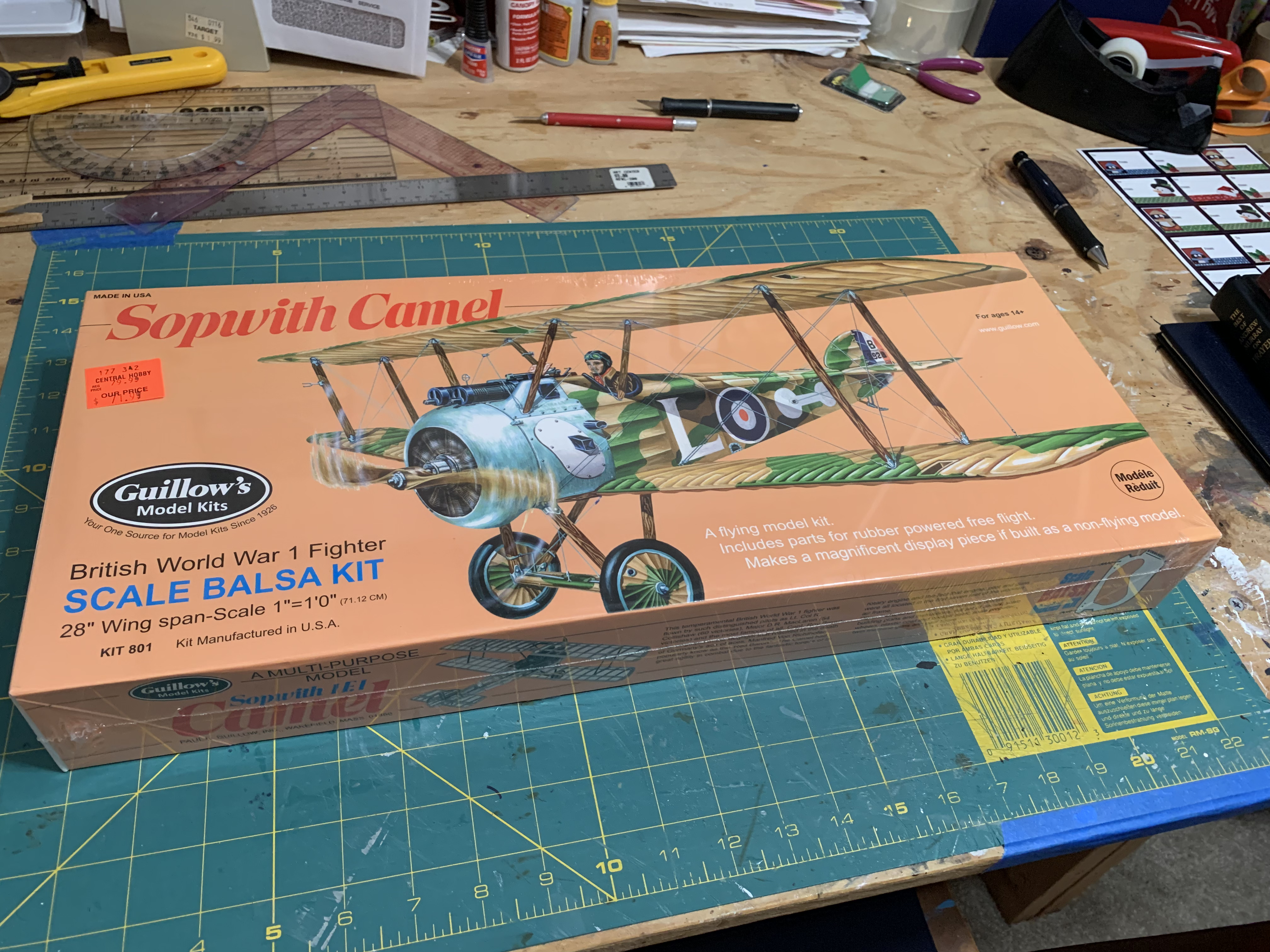
…but after already having poked a hole completely through the bottom wing while using a toothpick to touch-up some paint flaws, no telling what other damage I might inflict on this fragile model at the last stage.
For the final photo image of the model, I decided to pose a shot outdoors in as realistic a setting as I could, although with fake grass.
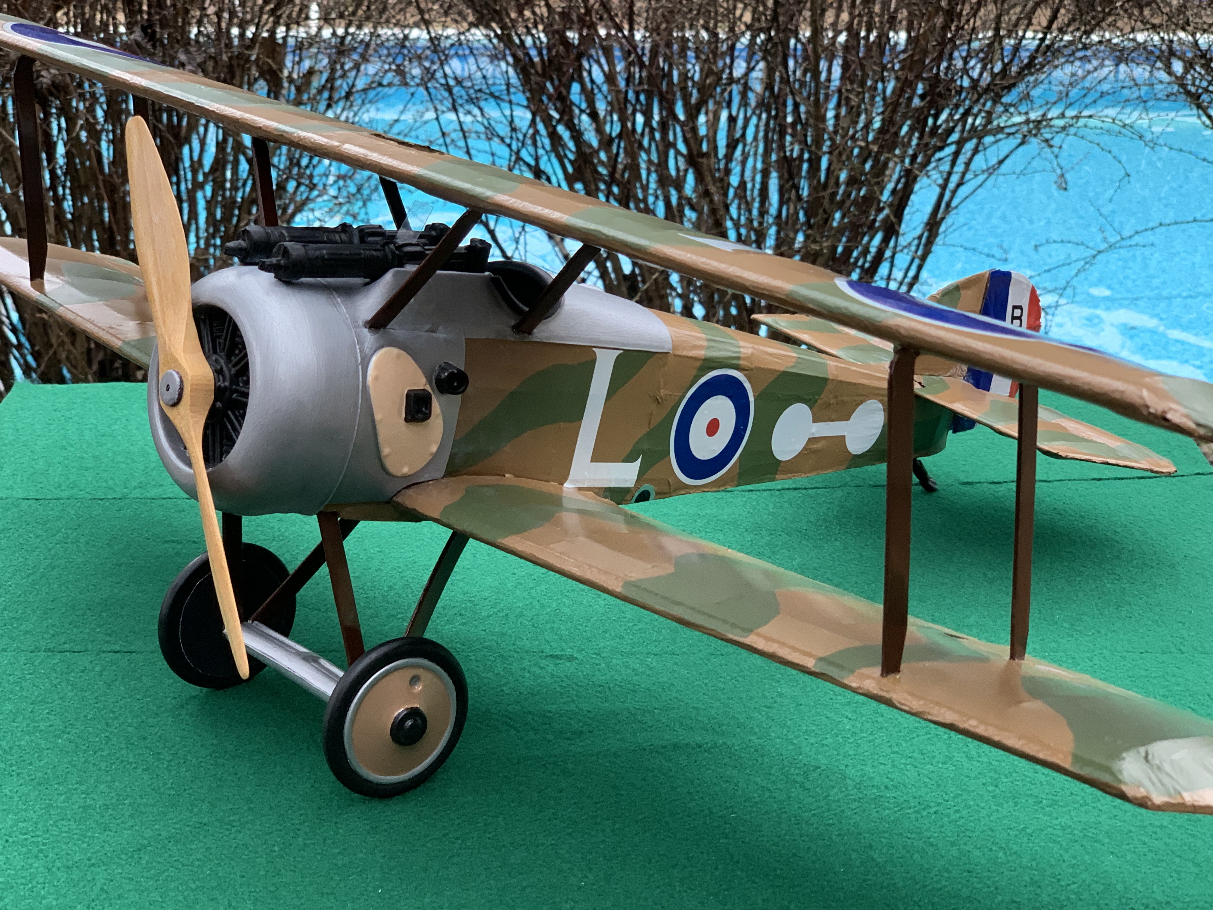
When I looked back through my photos chronicling the building of this model, I realized that my first photo was taken early in December 2021. These last images were taken mid-December 2022, so it took just over a year to build and finish this model. My progress throughout the year was interrupted multiple times as other projects and activities drew my attention away.
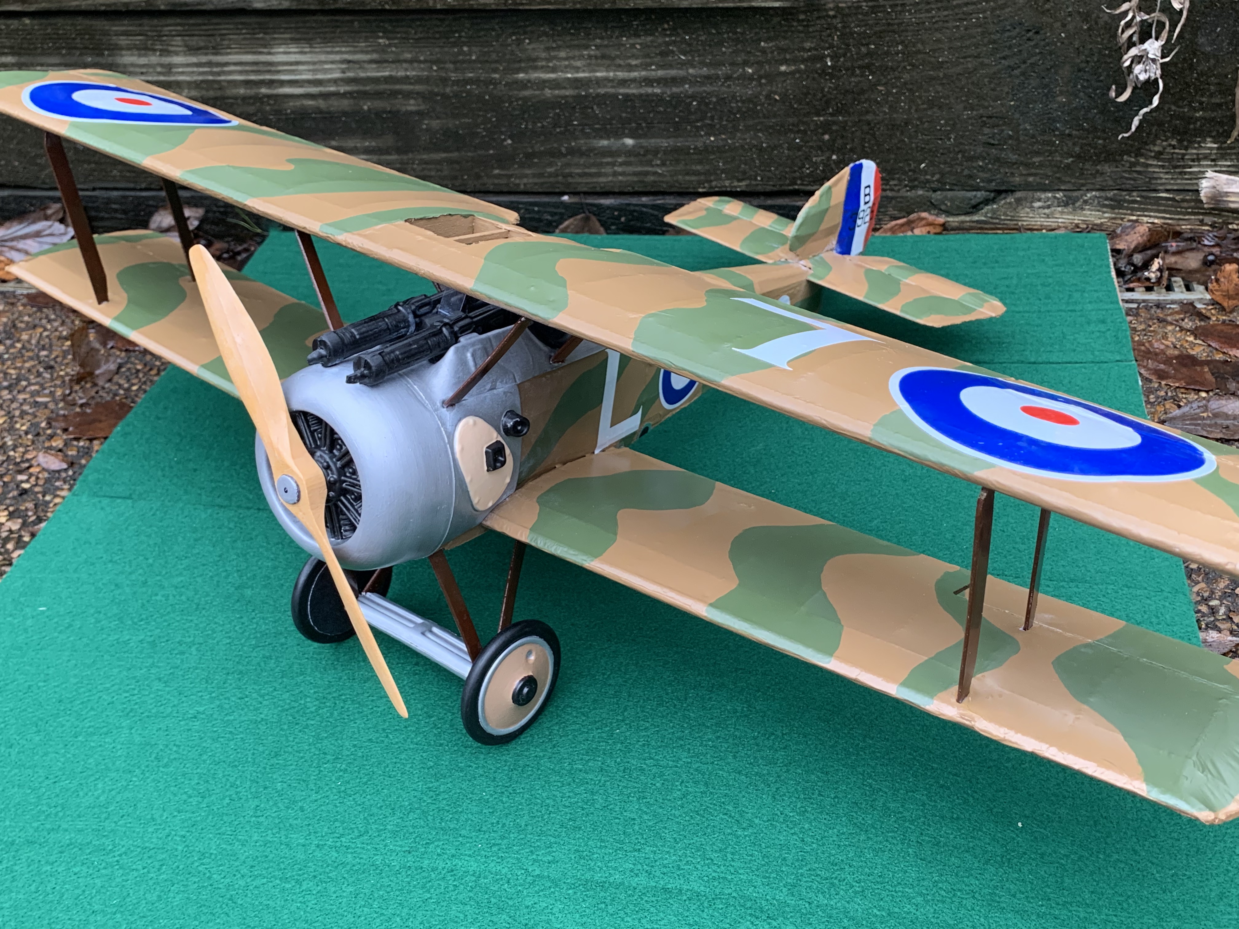
When I viewed the quality of my finished model, I knew it would never end up on display in a museum. While close scrutiny revealed many of its flaws, I also realized it would not end in the garbage heap either. Just as I had suspected when I purchased the kit, it was a lot of fun to build and relive some of that joy I had as a teenager building a balsa model airplane 50 years ago. But I must admit the series of challenges I faced and had to overcome tempered that enjoyment.
As such, I would close by saying it has definitely satisfied my desire to once again build a balsa and tissue model. However, I think going forward, I will continue to satiate my modeling appetite by working on doll houses with their all more forgiving and less fragile building materials. So, look for more miniature home construction posts in my future.
Categories
